Setting User Coordinate System
When the position of workpiece is changed or a robot program needs to be reused in multiple processing systems of the same type, you can create coordinate systems on the workpiece to simplify programming. There are 10 groups of User coordinate systems available, of which the first one is defined as the Base coordinate system by default and cannot be changed. And the others can be customized by users.
Note
When creating a User coordinate system, make sure that the reference coordinate system is the
predefined Base coordinate system. Namely, the User coordinate system icon should be User:
0 when creating a User coordinate system.
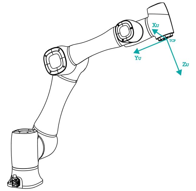
- Point: move to any point A to create the origin, and create a user coordinate system according to the robot’s default tool coordinate system.
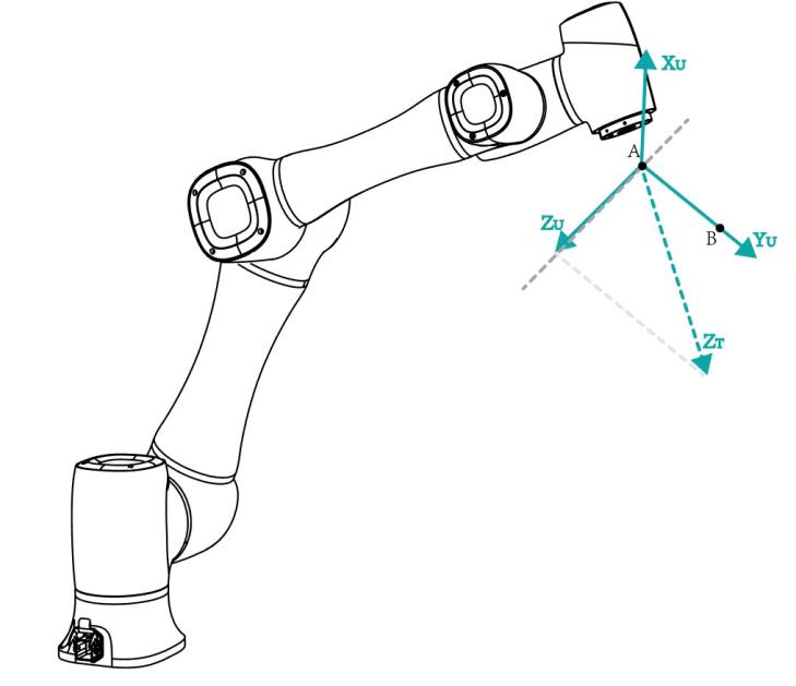
- Line: Confirm a straight line between any two points A and B. The direction from A to B is defined as the positive direction of Y-axis, the Z-axis of Tool coordinate system of which point A is the origin is projected into the vertical plane that confirmed by points A and point B, we can define it as the positive direction of Z-axis. and then the positive direction X-axis can be defined based on the right-hand rule.
- Area: User coordinate system is created by a three-point calibration method. Move the robot to three points A(x1, y1, z1), B(x2, y2, z2), and C(x3, y3, z3). Point A is defined as the origin. The line from point A to point B is defined as the positive direction of X-axis. The line that point C is perpendicular to the X-axis is defined as the position direction of Y-axis. The Z-axis is defined based on the right-hand rule.

Prerequisites
- The robot has been powered on.
- The robot motor has been enabled.
- The robot is in the Cartesian coordinate system.
Procedure
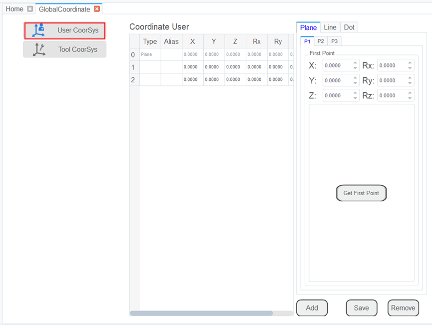
- Click Parameter > GlobalCoordinate > User CoorSys. The Coordinate User page will be displayed, as shown below.
Note
Rx, Ry, Rz are the orientation data, which are designated by rotating the TCP around the X, Y, Z axes under the selected User coordinate system.
- Jog the robot to the first point, the click Get First Point on the P1 tab to obtain the coordinates of the first point.
- Jog the robot to the second point, the click Get Second Point on the P2 tab to obtain the coordinates of the second point.
- Jog the robot to the third point, the click Get Third Point on the P3 tab to obtain the coordinates of the third point.
- Click Add and Save to generate the User 2 coordinate system.
- Select the User: 2 coordinate system for teaching and programming.