Configuration
This section walks you through the configurations that can be set on a Trossen AI arm. Properly configuring the arm for your application is crucial to ensure the arm operates as expected.
What You Need
To get started, please make sure you have gone through the Software Setup.
Overview
Depending on
when the change takes effect
whether the changed configuration is reset to default at the next boot
the configurations are divided into four categories as given in the following table.
Immediately Applied |
Applied at Next Boot |
|
|---|---|---|
Remain Unchanged After Reboot |
||
Reset to Default After Reboot |
The driver provides methods to get and set these configurations. An example of a configuration script is given here.
// Include the header files
#include "libtrossen_arm/trossen_arm.hpp"

int main(int argc, char** argv)
{
  // Create a driver object
  trossen_arm::TrossenArmDriver driver;

  // Configure the driver
  // This configuration is mandatory, including
  // - model of the arm
  // - end effector properties
  // - IP address of the arm
  // - whether to clear the existing error state if any
  // - Timeout for connection to the arm controller's TCP server in seconds
  driver.configure(...);

  // Get/set some configurations if needed
  // Here xxx can be
  // - factory_reset_flag
  // - ip_method
  // - manual_ip
  // - dns
  // - gateway
  // - subnet
  // - joint_characteristics
  // - effort_corrections
  // - friction_transition_velocities
  // - friction_constant_terms
  // - friction_coulomb_coefs
  // - friction_viscous_coefs
  // - end_effector
  // - joint_modes
  // - joint_limits
  // - motor_parameters
  // - algorithm_parameter
  auto xxx = driver.get_xxx(...);
  driver.set_xxx(...);
}
# Import the driver
import trossen_arm

if __name__ == "__main__":
    # Create a driver object
    driver = trossen_arm.TrossenArmDriver()

    # Configure the driver
    # This configuration is mandatory, including
    # - model of the arm
    # - end effector properties
    # - IP address of the arm
    # - whether to clear the existing error state if any
    # - Timeout for connection to the arm controller's TCP server in seconds
    driver.configure(...)

    # Get/set some configurations if needed
    # Here xxx can be
    # - factory_reset_flag
    # - ip_method
    # - manual_ip
    # - dns
    # - gateway
    # - subnet
    # - joint_characteristics
    # - effort_corrections
    # - friction_transition_velocities
    # - friction_constant_terms
    # - friction_coulomb_coefs
    # - friction_viscous_coefs
    # - end_effector
    # - joint_modes
    # - joint_limits
    # - motor_parameters
    # - algorithm_parameter
    xxx = driver.get_xxx(...)
    driver.set_xxx(...)
Tip
We provide methods to exchange persistent configurations via a YAML file. Check out the configuration_in_yaml demo for more details.
Default Values
The default values are given in default_configurations_wxai_v0.yaml.
Note
The default value of the Joint Characteristics is calibrated at manufacturing and different for each arm.
How They Work?
Here is a breakdown of how the configurations affect the behavior of the arm.
factory_reset_flag
If the factory_reset_flag is set to true, all configurations are reset to their factory default values at the next boot.
Choices: bool
Ethernet Configuration
At startup, the arm controller tries to connect to the network. The procedure is as follows.
        flowchart LR
    A(Power on) --> B{ip_method?}
    B -->|dhcp| C(Acquire IP from DHCP server)
    B -->|manual| D(Set up ethernet according to the configurations)
    C --> E{success?}
    E -->|yes| F(Set up ethernet as DHCP server directs)
    E -->|no| D
ip_method
The IP method specifies whether the arm controller acquires its IP address from a DHCP server or uses a static IP address.
Choices: trossen_arm::IPMethod
Note
If the IP method is set to trossen_arm::IPMethod::dhcp, we expect a DHCP server to be present in the network.
It can be a router or a computer with a DHCP server running.
manual_ip, dns, gateway, subnet
If the IP method is set to trossen_arm::IPMethod::manual, the manual IP address, DNS, gateway, and subnet are used.
Ranges: valid IPv4 addresses as strings
Joint Characteristics
The joint characteristics affect the behavior of each joint.
effort_corrections
The trossen_arm::JointCharacteristic::effort_correction maps a motor’s effort unit to the standard unit, i.e., Nm and N.
To give an example, in external effort mode, the command sent to the motor is given by the following expression.
Vice versa, the effort returned by the driver is given by the following expression.
Range: \([0.2, 5.0]\)
friction_transition_velocities, friction_constant_terms, friction_coulomb_coefs, and friction_viscous_coefs
We model joint friction as a function of velocity and effort of three components: Coulomb, viscous, and constant.
The Coulomb friction is proportional to the magnitude of the effort.
The viscous friction is proportional to the velocity.
The constant friction is independent of the velocity and effort.
To deal with the discontinuity when the direction of the velocity changes, we use a linear transition characterized by the transition velocity.
The resulting compensation effort is given below, where \(\text{effort}_\text{inverse_dynamics}\) is the effort computed by inverse dynamics.
Each controller-arm pair comes with calibrated effort corrections and friction parameters as defaults. They should work decently for most applications. However, you can always fine-tune them according to personal preferences.
Here is a guideline to tune the effort corrections and friction parameters.
Put the arm in gravity compensation, i.e., all external efforts are zero
Tune the joints one by one from gripper to base
Increase
trossen_arm::JointCharacteristic::effort_correctionif the links onwards are pulled down by gravityMove the joint at low velocity and increase the
trossen_arm::JointCharacteristic::friction_coulomb_coefif the resistance is stronger when the joint is compensating for gravity than in a balanced positionMove the joint at varying velocities and increase the
trossen_arm::JointCharacteristic::friction_viscous_coefif there’s more resistance at higher velocityIncrease the
trossen_arm::JointCharacteristic::friction_constant_termto uniformly reduce the resistance up til the joint starts moving spontaneouslyIncrease the
trossen_arm::JointCharacteristic::friction_transition_velocityif quiet operation and large stiction is preferred over reduced stiction with high-frequency oscillations
Ranges:
trossen_arm::JointCharacteristic::friction_transition_velocity: \(\mathbb{R}_{\gt 0}\)others: \(\mathbb{R}\)
position_offset
The trossen_arm::JointCharacteristic::position_offset offsets the joint position to account for homing error.
It is added to the command sent to the motor and subtracted from the feedback received from the motor.
\(\text{position}_\text{motor} = \text{position} + \text{position_offset}\)
where \(\text{position}_\text{motor}\) is used by the motor and \(\text{position}\) is intended to match the kinematic model definition.
All transactions of positions in the driver API refer to \(\text{position}\), e.g., trossen_arm::RobotOutput::Cartesian::positions, trossen_arm::RobotOutput::Joint::All::positions, trossen_arm::TrossenArmDriver::set_cartesian_positions(), and trossen_arm::TrossenArmDriver::set_all_positions().
Range: \(\mathbb{R}\)
Warning
Since these configurations are arm specific, mixed usage of controller and arm with different serial numbers may cause deterioration in performance.
End Effector
The trossen_arm::EndEffector allow the usage of different end effectors.
It’s important to match the end effector properties with the actual end effector attached to the arm.
Otherwise, the controller won’t be able to properly compensate for the end effector’s weight and inertia.
Tip
End effector variants supported by Trossen Robotics are provided in trossen_arm::StandardEndEffector.
Tip
New in version 1.8.3: the original rack-and-pinion end effector can be removed or replaced with a custom end effector.
On startup, the controller checks if the gripper motor exists.
If the motor is not detected, it assumes that the gripper assembly has been removed.
An example with nothing mounted at the flange is given by trossen_arm::StandardEndEffector::no_gripper.
What works:
Inverse dynamics for the arm joints, e.g., gravity and friction compensations
Input and output of the arm joints, e.g., Cartesian and joint positions, velocities, and efforts
What won’t work:
Input and output of the end effector
Link Properties
The trossen_arm::Link members of the end effector define the three links of an end effector.
trossen_arm::EndEffector::palm: the whole end effector excluding the fingerstrossen_arm::EndEffector::finger_left: the finger on the left sidetrossen_arm::EndEffector::finger_right: the finger on the right side
The definition of trossen_arm::Link follows the URDF convention.
And the left and right sides are defined with respect to the arm’s perspective, i.e., observing from the base to the end effector when the joints are in home positions.
A custom end effector should be treated as a single link defined by trossen_arm::EndEffector::palm.
The finger links are ignored in this case.
Ranges:
trossen_arm::Link::mass: \(\mathbb{R}\)trossen_arm::Link::inertia: \(\mathbb{R}^9\)trossen_arm::Link::origin_xyz: \(\mathbb{R}^3\)trossen_arm::Link::origin_rpy: \(\mathbb{R}^3\)
Finger Offsets
The offsets of the left and right fingers define the home position specific to the fingers.
trossen_arm::EndEffector::offset_finger_left: the offset from the palm center to the left carriage center in m with the fingers closedtrossen_arm::EndEffector::offset_finger_right: the offset from the palm center to the right carriage center in m with the fingers closed
For a custom end effector, these offsets are ignored.
Ranges: \(\mathbb{R}\)
pitch_circle_radius
The pitch circle radius defines the transmission ratio of the rack and pinion mechanism of the original end effector.
trossen_arm::EndEffector::pitch_circle_radius specifies pitch circle radius of the pinion of the end effector.
For a custom end effector, this value is ignored.
Range: \(\mathbb{R}\)
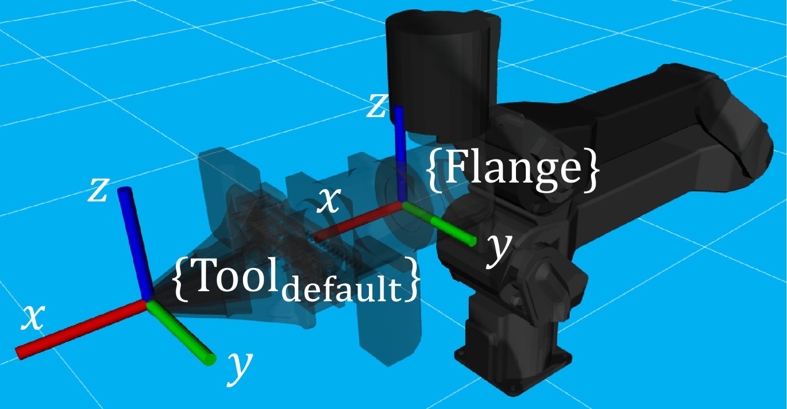
t_flange_tool
trossen_arm::EndEffector::t_flange_tool defines the tool frame pose measured in the flange frame as shown in the image below.
Note
The first 3 elements are the translation and the last 3 elements are the angle-axis representation of the rotation
Range: \(\mathbb{R}^6\)
Joint Modes
The joint modes define the mode of operation of each joint.
Choices: trossen_arm::Mode
Joint Limits
The joint limits define the operating limits of each joint.
The block diagram of the control loop of the motor is given below.
        flowchart TD
    A[ ] -->|desired position| B[clip]
    style A fill:transparent, stroke:transparent
    B -->|clipped desired position| C((sum))
    C -->|position error| D[PID]
    D -->|desired velocity| E((sum))
    E --> F[clip]
    F -->|clipped desired velocity| G((sum))
    G -->|velocity error| H[PID]
    H -->|desired effort| I((sum))
    I --> J[clip]
    J -->|clipped desired effort| K((motor))

    L[ ] -->|feedforward velocity| E
    style L fill:transparent, stroke:transparent
    M[ ] -->|feedforward effort| I
    style M fill:transparent, stroke:transparent

    K -->|actual position| N{check}
    N -->|within limit| C
    K -->|actual velocity| O{check}
    O -->|within limit| G

    N -->|beyond limit| P[error]
    O -->|beyond limit| P
When the controller receives a command from the driver, it generates the command for a motor by clipping to the min and max limits.
position = min(max(position,
trossen_arm::JointLimit::position_min),trossen_arm::JointLimit::position_max)velocity = min(velocity,
trossen_arm::JointLimit::velocity_max)effort = min(effort,
trossen_arm::JointLimit::effort_max)
When the controller receives a feedback from the motor, it triggers an error if anything is beyond the max and min limits padded by the tolerances.
position <
trossen_arm::JointLimit::position_max+trossen_arm::JointLimit::position_toleranceposition >
trossen_arm::JointLimit::position_min-trossen_arm::JointLimit::position_tolerancevelocity <
trossen_arm::JointLimit::velocity_max+trossen_arm::JointLimit::velocity_toleranceeffort <
trossen_arm::JointLimit::effort_max+trossen_arm::JointLimit::effort_tolerance
For reference, we can choose the limits as follows.
When creating a new application script, we need
the min and max limits to be above the expected motion range
the tolerances to be 0.0 to catch any unexpected behavior
When the application script is well tested, we need
the min and max limits to be above the expected motion range
the tolerances to be some positive values to avoid false positives
Range: \(\mathbb{R}\)
Motor Parameters
The motor parameters define the control parameters of each motor.
As shown in the block diagram above, each motor trossen_arm::MotorParameter has two PID controllers for position and velocity regulation.
By setting different parameters in trossen_arm::PIDParameter, we can achieve the behavior of different trossen_arm::Mode.
A guideline to tune the motor parameters is given below.
-
Start with all parameters set to zero
Set the position and velocity loop
trossen_arm::PIDParameter::kpto small positive values such that the joint starts moving towards the desired positionIncrease the position loop
trossen_arm::PIDParameter::kpuntil the joint starts to overshootIncrease the velocity loop
trossen_arm::PIDParameter::kpuntil the overshoot disappearsRepeat steps 3 and 4 until the joint starts oscillating
Decrease both position and velocity loop
trossen_arm::PIDParameter::kp, e.g., half the valuesSet the velocity loop
trossen_arm::PIDParameter::imaxto a reasonable value, e.g., rated torque of the motorIncrease the velocity loop
trossen_arm::PIDParameter::kiuntil the joint starts to overshootDecrease the velocity loop
trossen_arm::PIDParameter::ki, e.g., half the value
-
Use the same parameters as in
trossen_arm::Mode::positionZero out all position loop parameters
Set the velocity loop
trossen_arm::PIDParameter::imaxto a reasonable value, e.g., max torque of the motorIncrease the velocity loop
trossen_arm::PIDParameter::kiuntil the joint starts to oscillate
trossen_arm::Mode::velocity,trossen_arm::Mode::external_effort, andtrossen_arm::Mode::effort:Use the same parameters as in
trossen_arm::Mode::positionZero out the velocity loop
trossen_arm::PIDParameter::kiandtrossen_arm::PIDParameter::imax
Ranges: \(\mathbb{R}\)
Algorithm Parameter
This configuration defines the parameters used for robotic algorithms.
trossen_arm::AlgorithmParameter::singularity_threshold:When moving in Cartesian space, an error is triggered if the arm is close to a singular configuration. The threshold is defined below.
\[\text{singularity_threshold} \lt \frac{\min_i {|\text{pivot}_i|}}{\max_i {|\text{pivot}_i|}}\]where \(\text{pivot}_i\) is the \(i\)’th pivot of the QR decomposition of the Jacobian that maps joint velocities to Cartesian velocities.
Range: \(\mathbb{R}\)
What’s Next?
Now that the arm is configured, an assorted collection of Demo Scripts is available to help you get started with controlling the arm.