Stationary ALOHA Hardware Setup
If you need any assistance or have questions about this process, please contact our customer service.
Tip
Building tip: Don’t tighten bolts all the way until every bolt is partially installed.
Assembly Guide
Video Overview
Steps
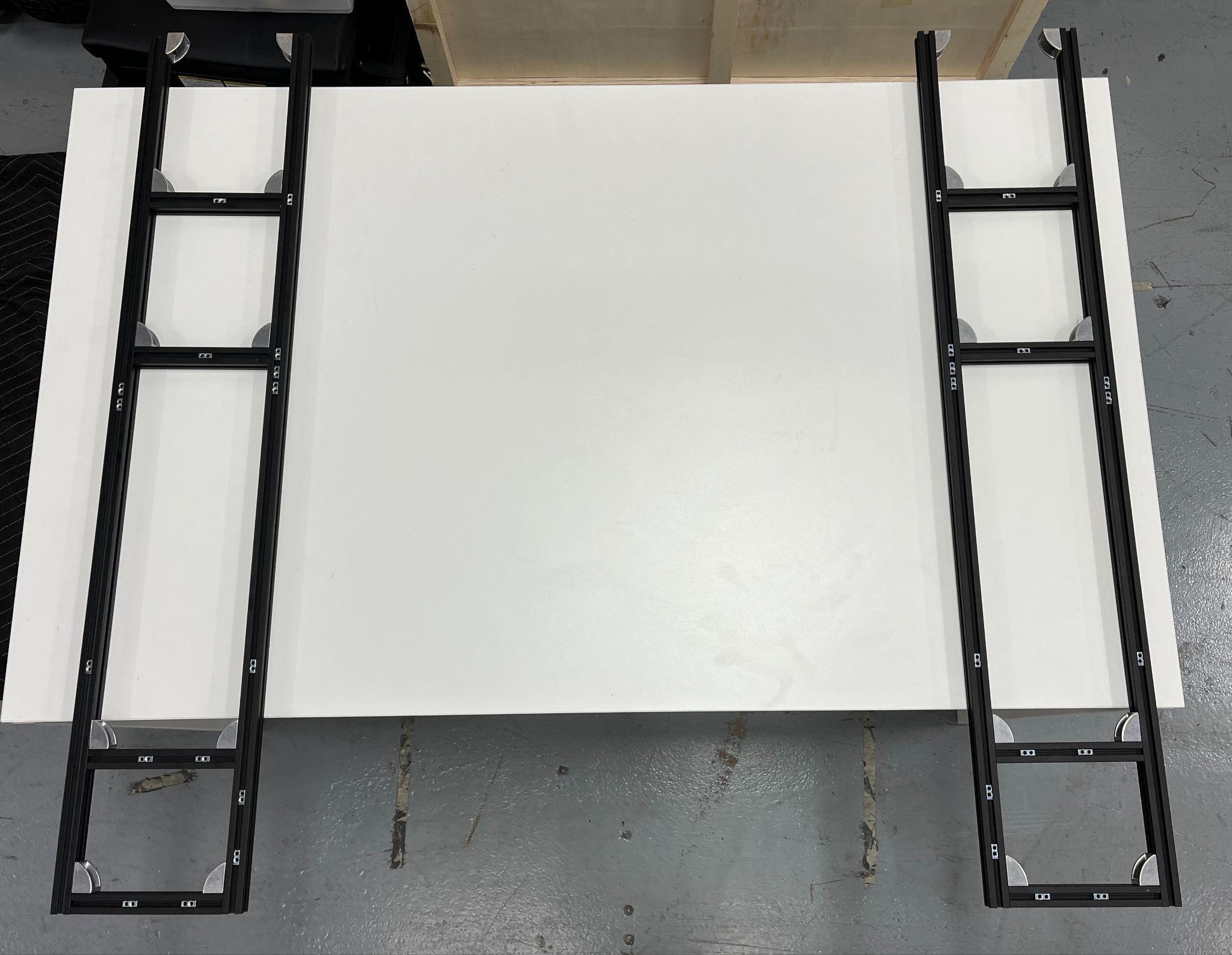
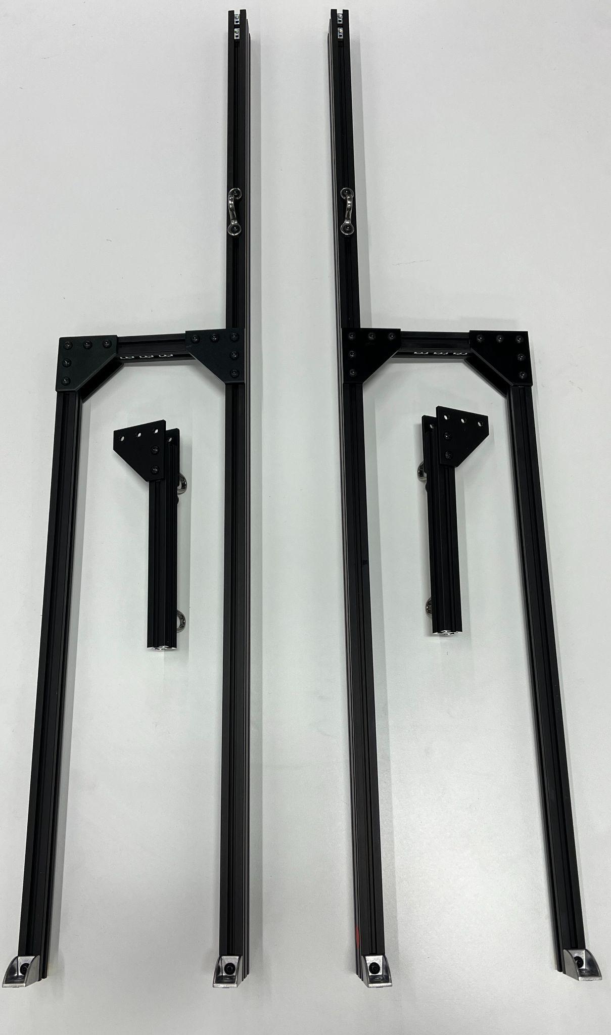
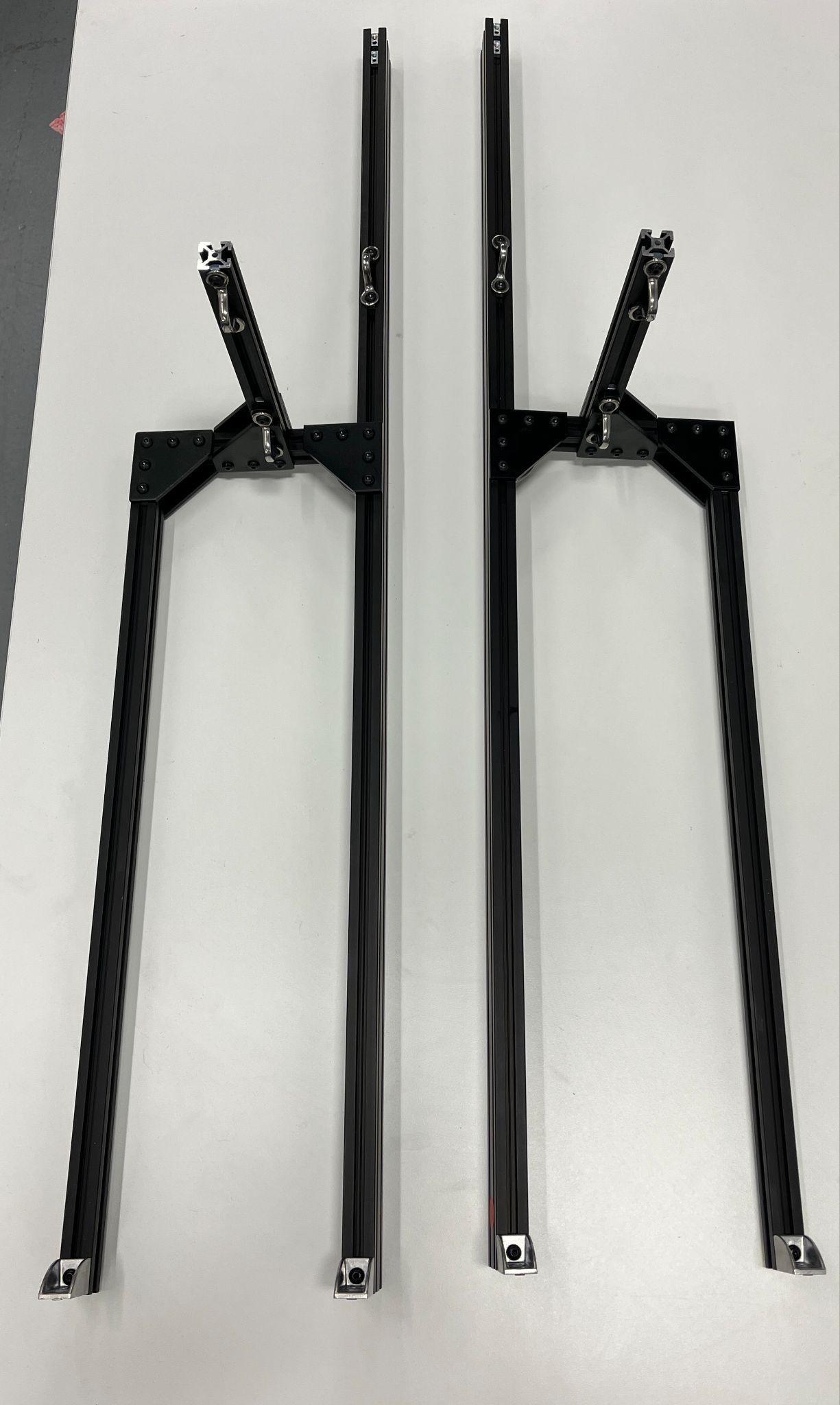
1) Lay Out AA/AB Sub-Assembly on Surface
Use the orientation of T-nuts to determine which side each one goes on.
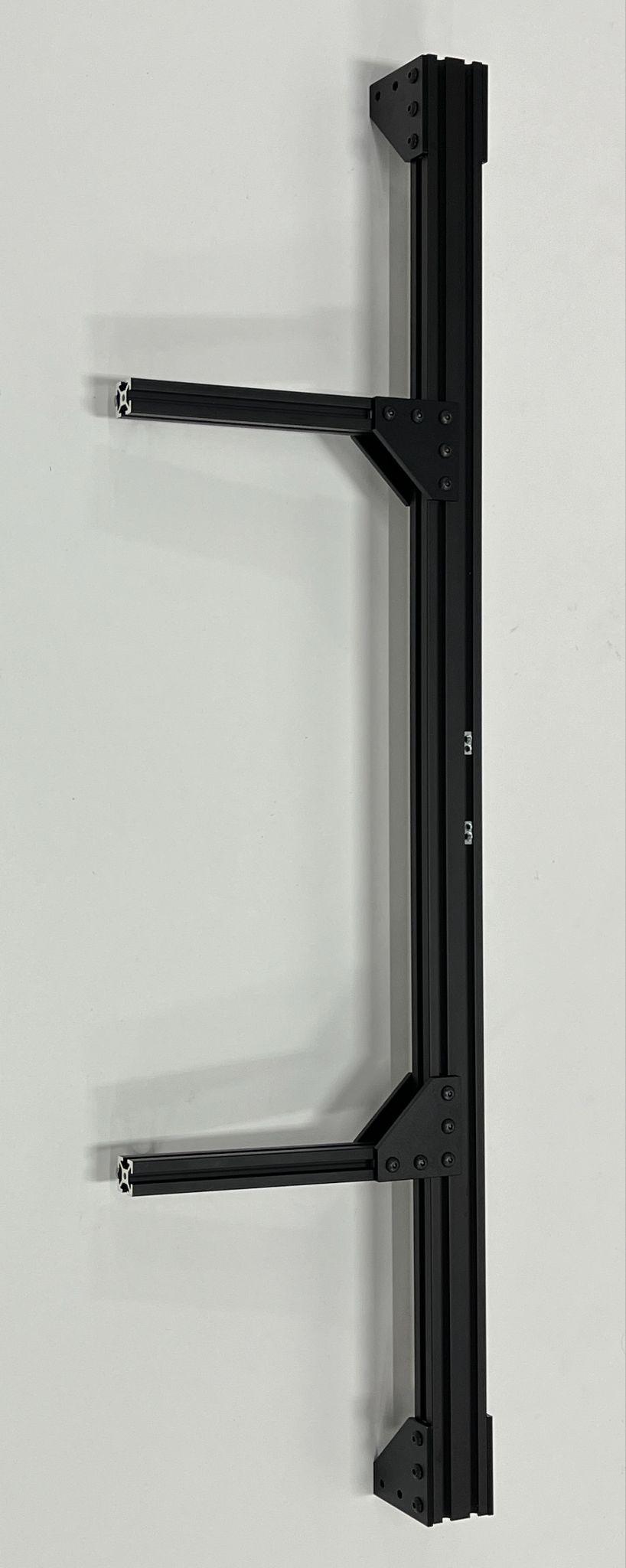
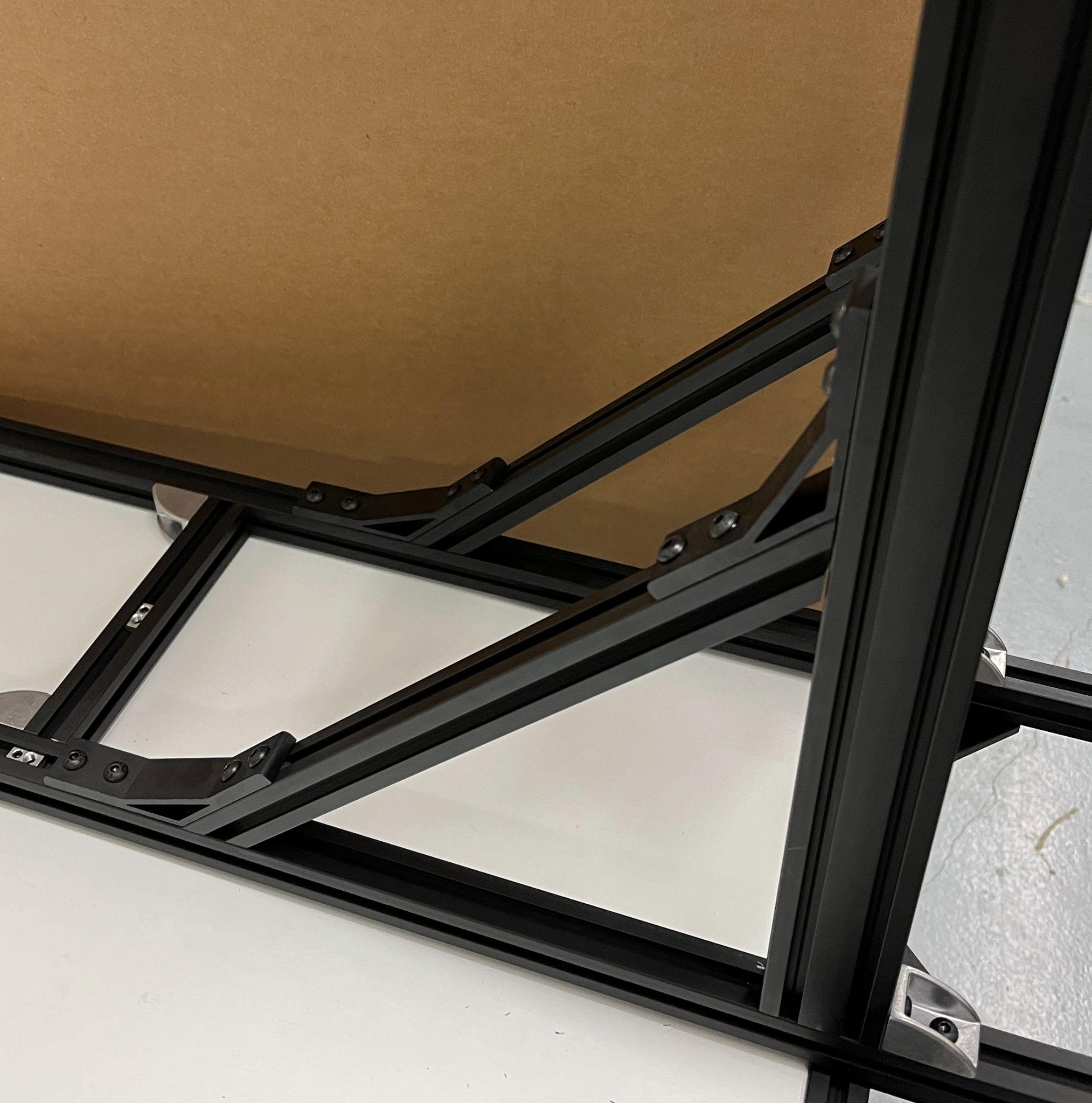
2) Attach Front and Back 1220 Bars to AA/AB Sub-Assembly
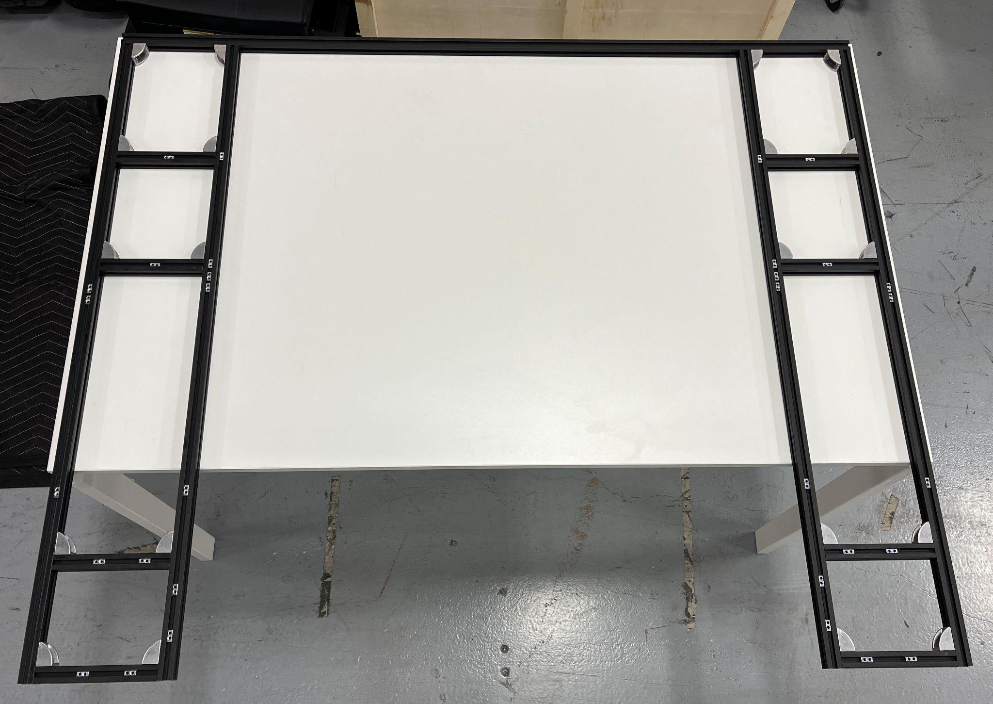
AA/AB SUB-ASSEMBLY with BACK 1220 attached.
|
|
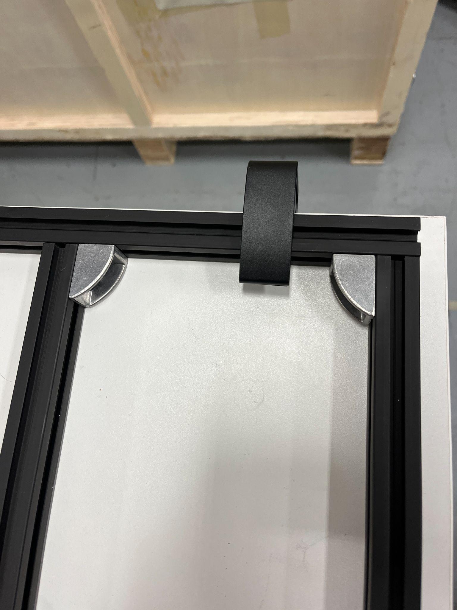
Attach AA/AB SUB-ASSEMBLIES to BACK 1220 BAR with (4x) M5x10s bolts at these 20/30 BRACKETS.
Upside-Down AA/AB SUB-ASSEMBLY with FRONT 1220 attached.
|
|
Install (8x) M5x10s bolts at these CORNER PLATES.
3) Attach 200 Bars to H Bars and 890 Bar
|
|
Use (12x) M5x10s bolts to attach (2) 200 P BARS to H BARS.
Use (8x) M5x10s bolts to attach (2) 200 G BARS to 890 BAR.
4) Attach 890 Bar on top of the two H Bars
Use (8x) M5x10s bolts to install 890 BAR to top of H BARS.
5) Attach H Bars to AA/AB Sub-Assembly
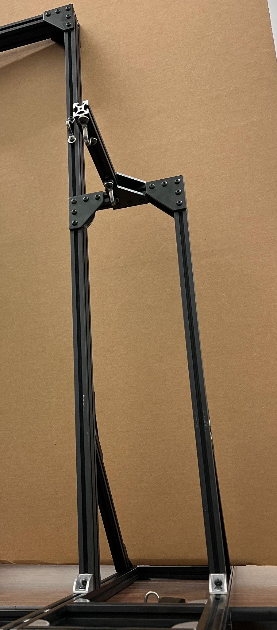
H BARS fully installed onto AA/AB SUB-ASSEMBLY
|
|
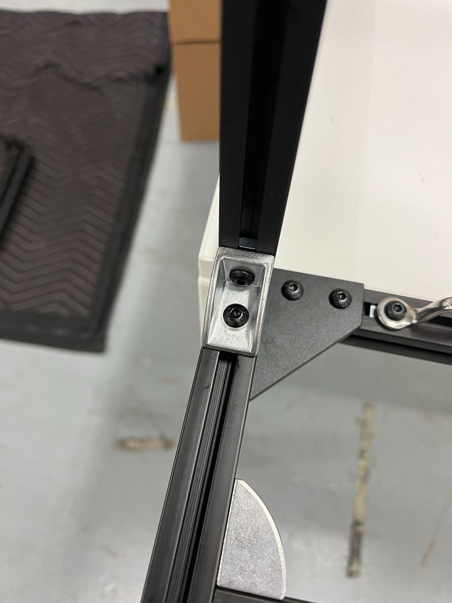
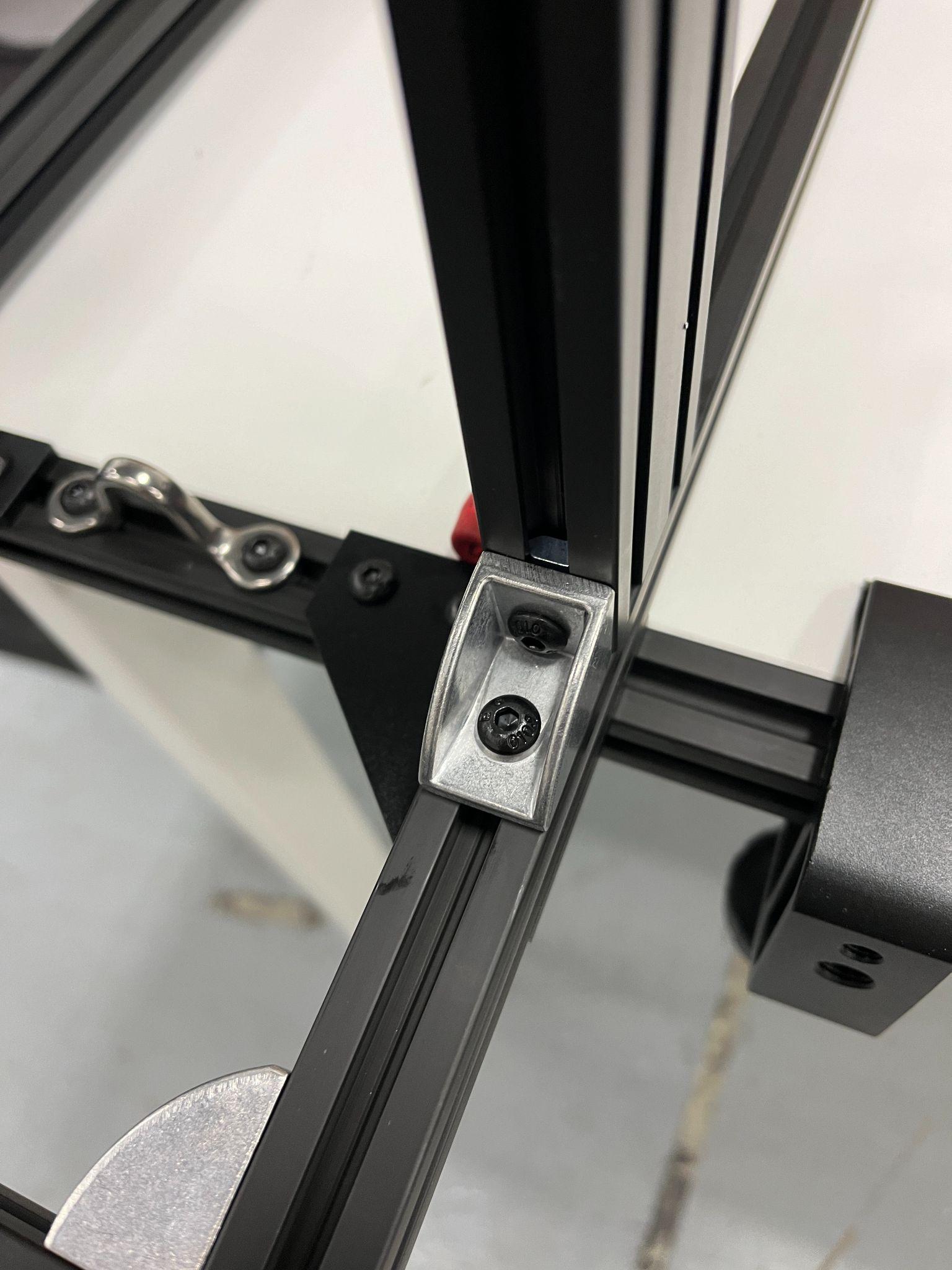
Install (2x) M5x10s bolts at these 20/30 BRACKETS to keep H BAR in place.
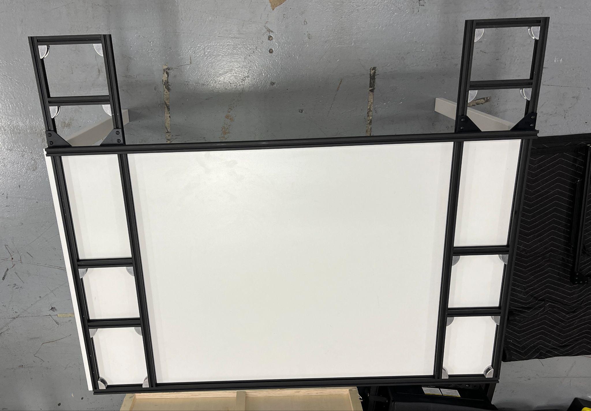
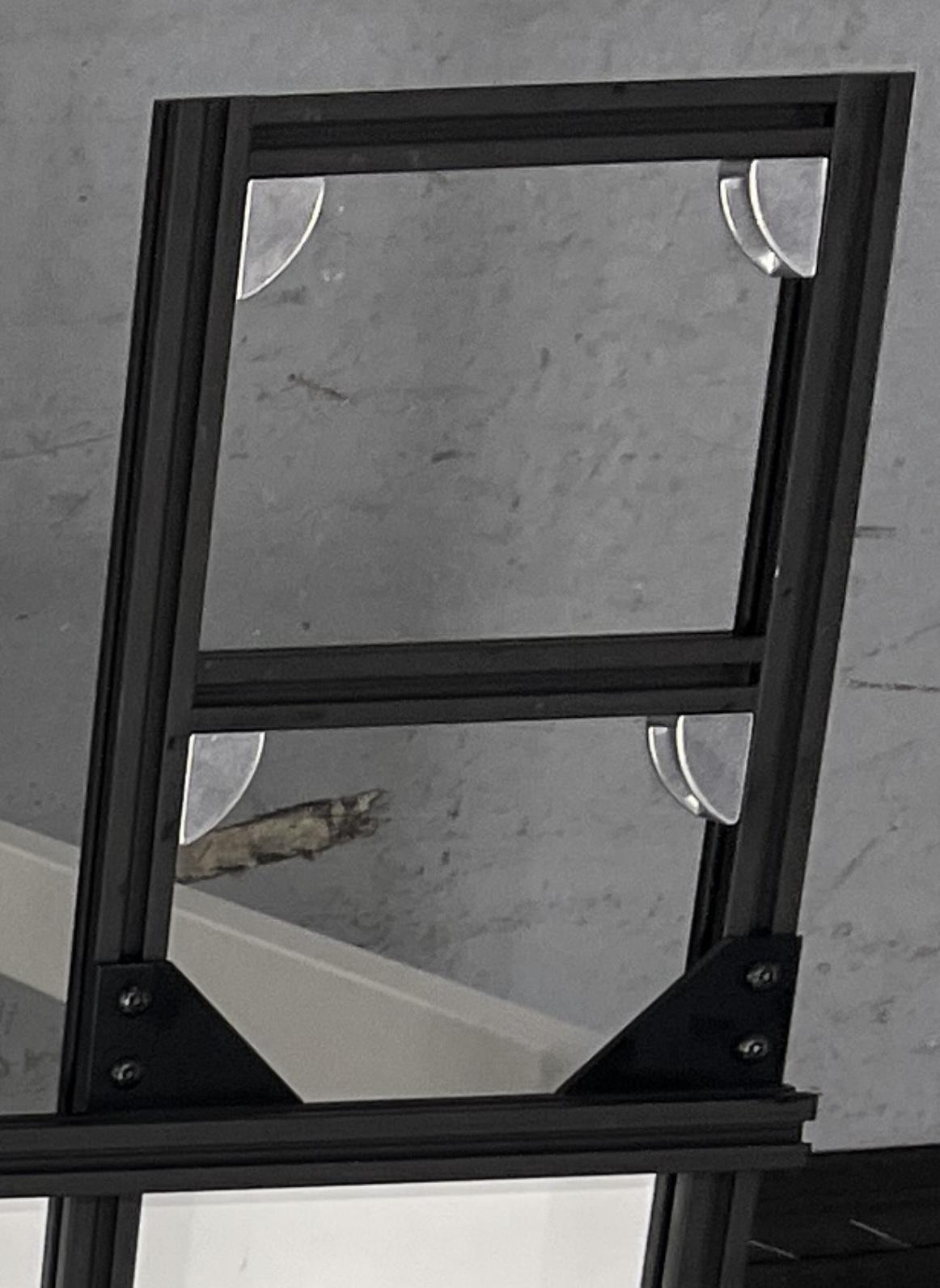
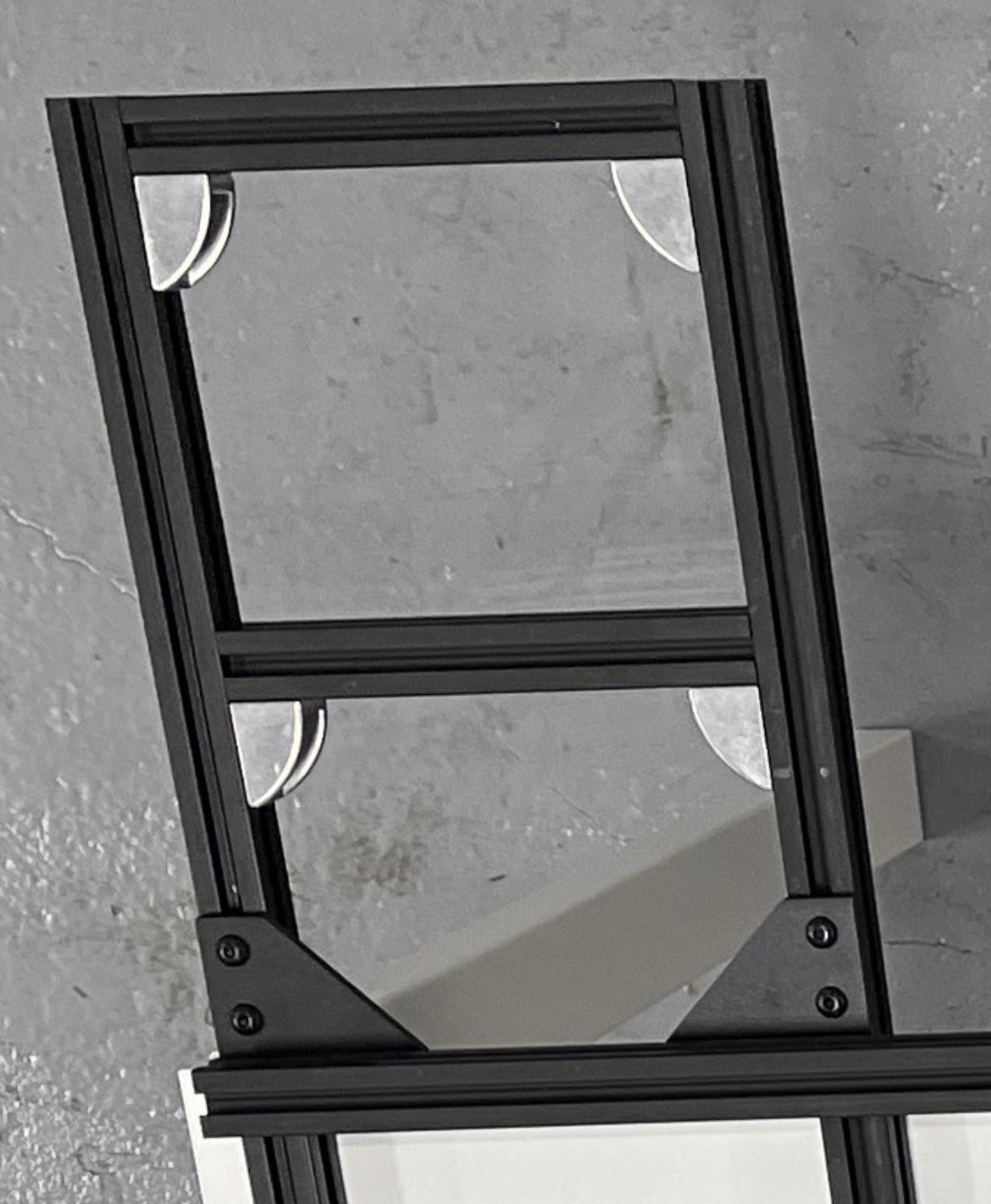
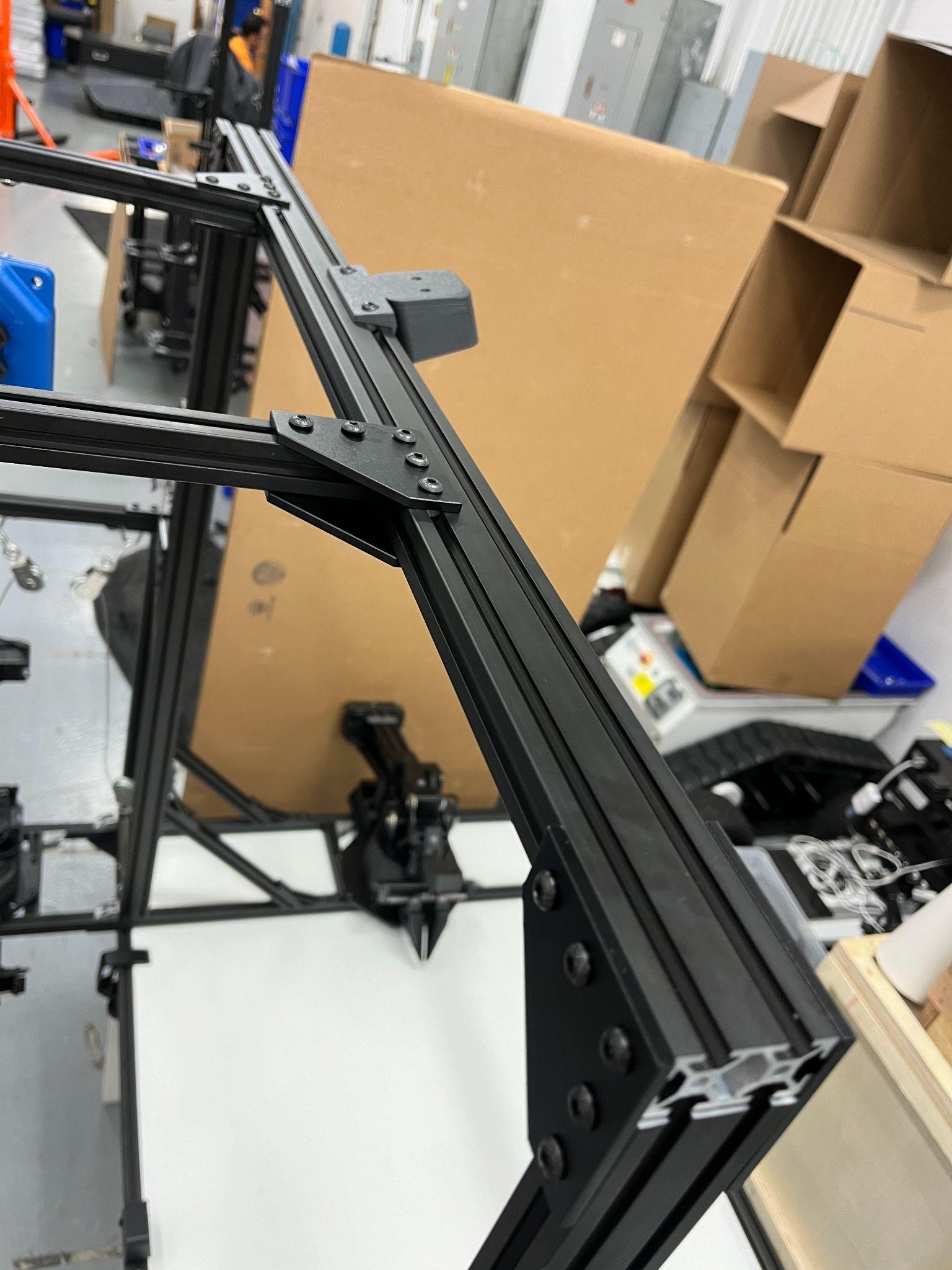
6) Attach 305 Bars on back of H Bar and top of AA/AB Sub-Assembly
Install (8x) M5x12s bolts to CORNER BRACKETS to connect H-BAR and AA/AB SUB-ASSEMBLY.
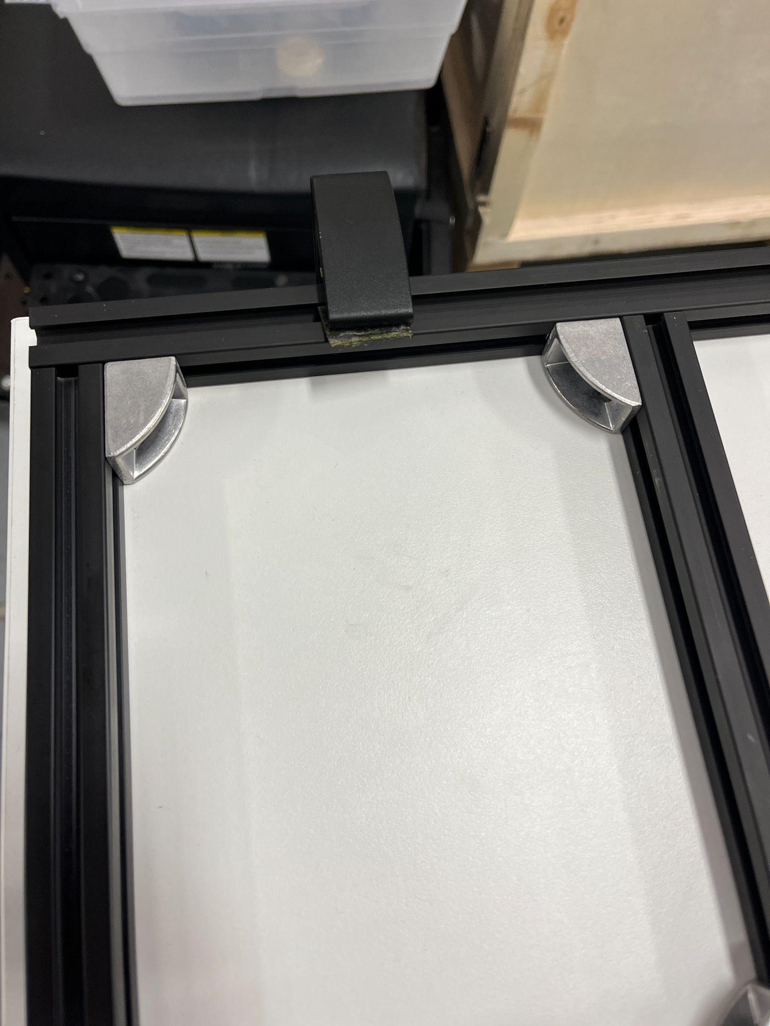
7) Clamp frame to stationary table
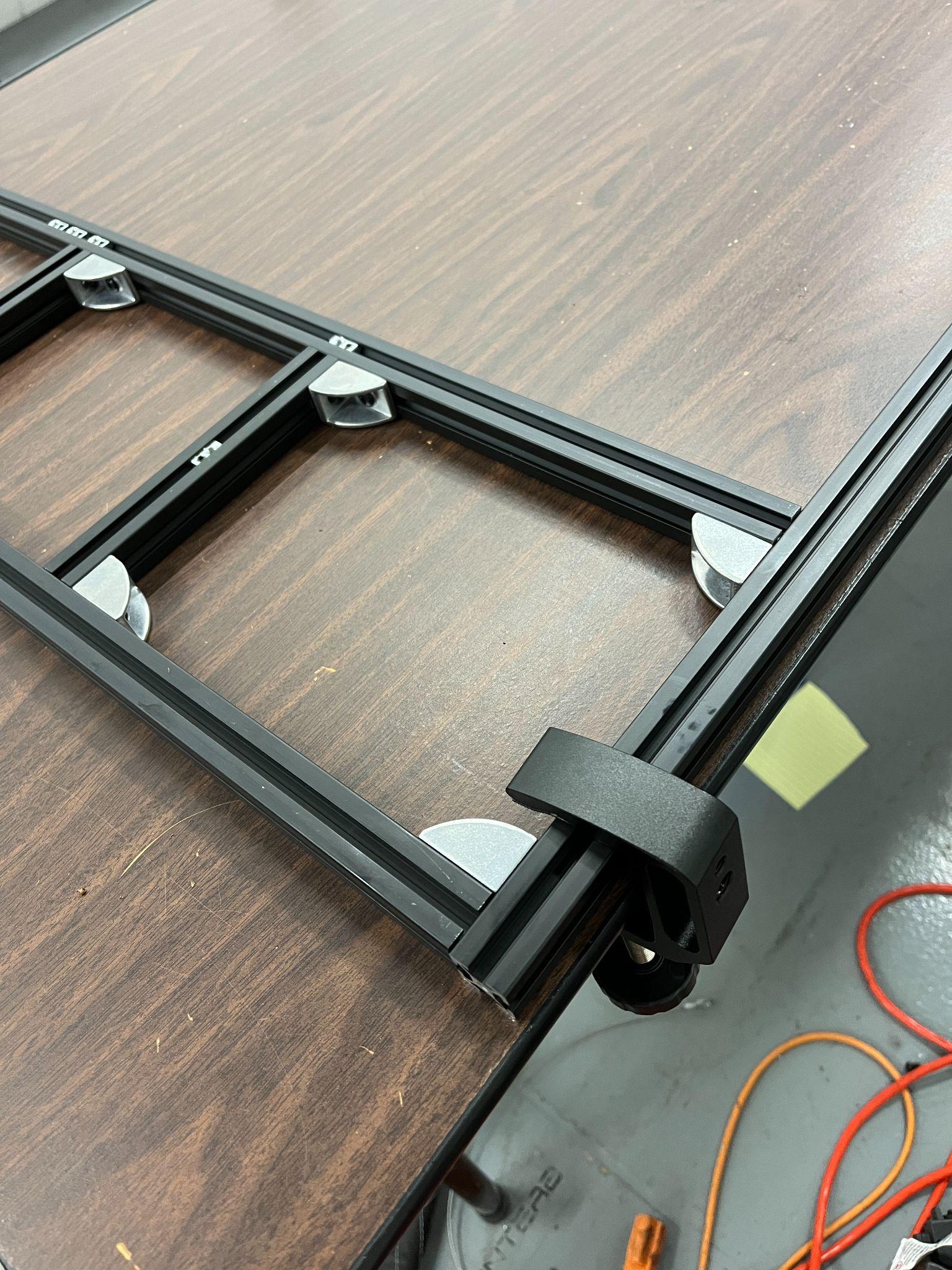
|
|
8) Install WidowX arms to the front of the Aloha Stationary
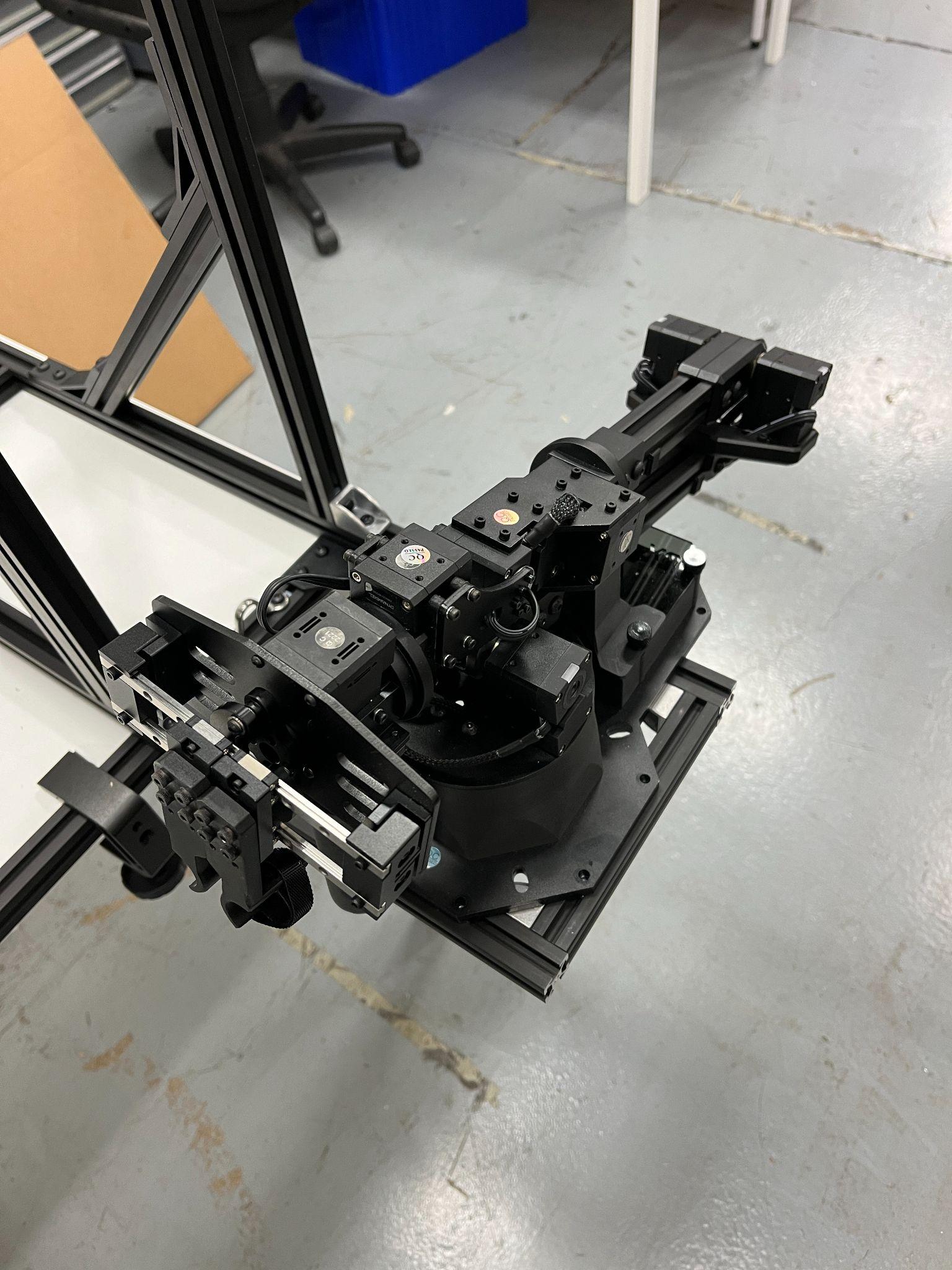
WidowX Arm placed on right side location
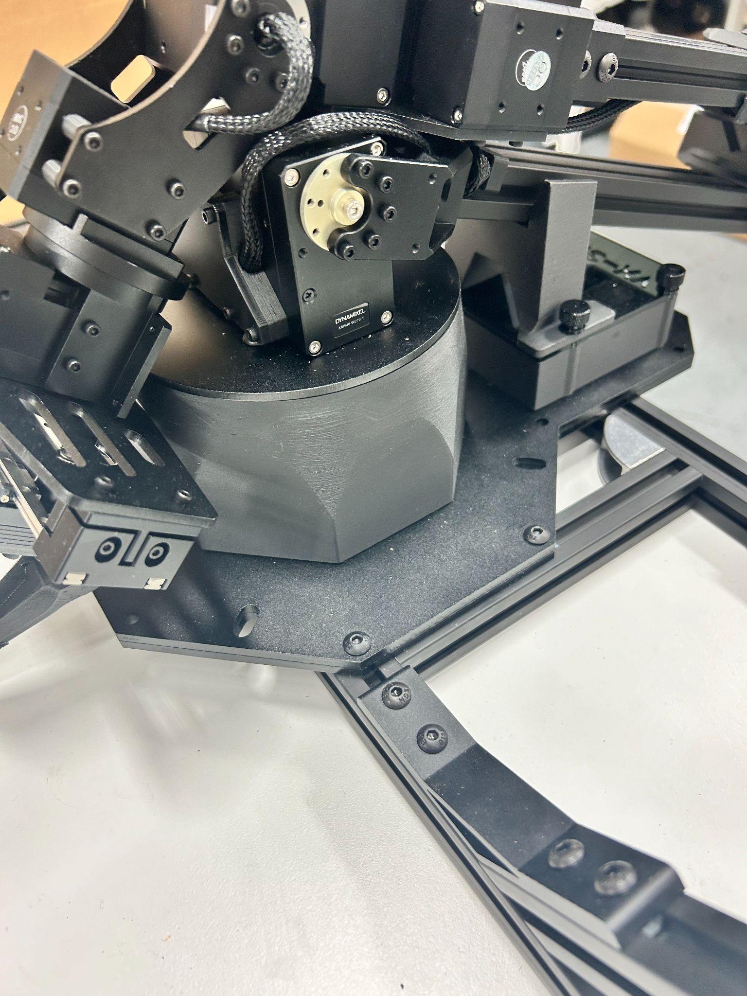
9) Install ViperX arms to the back of the Aloha Stationary
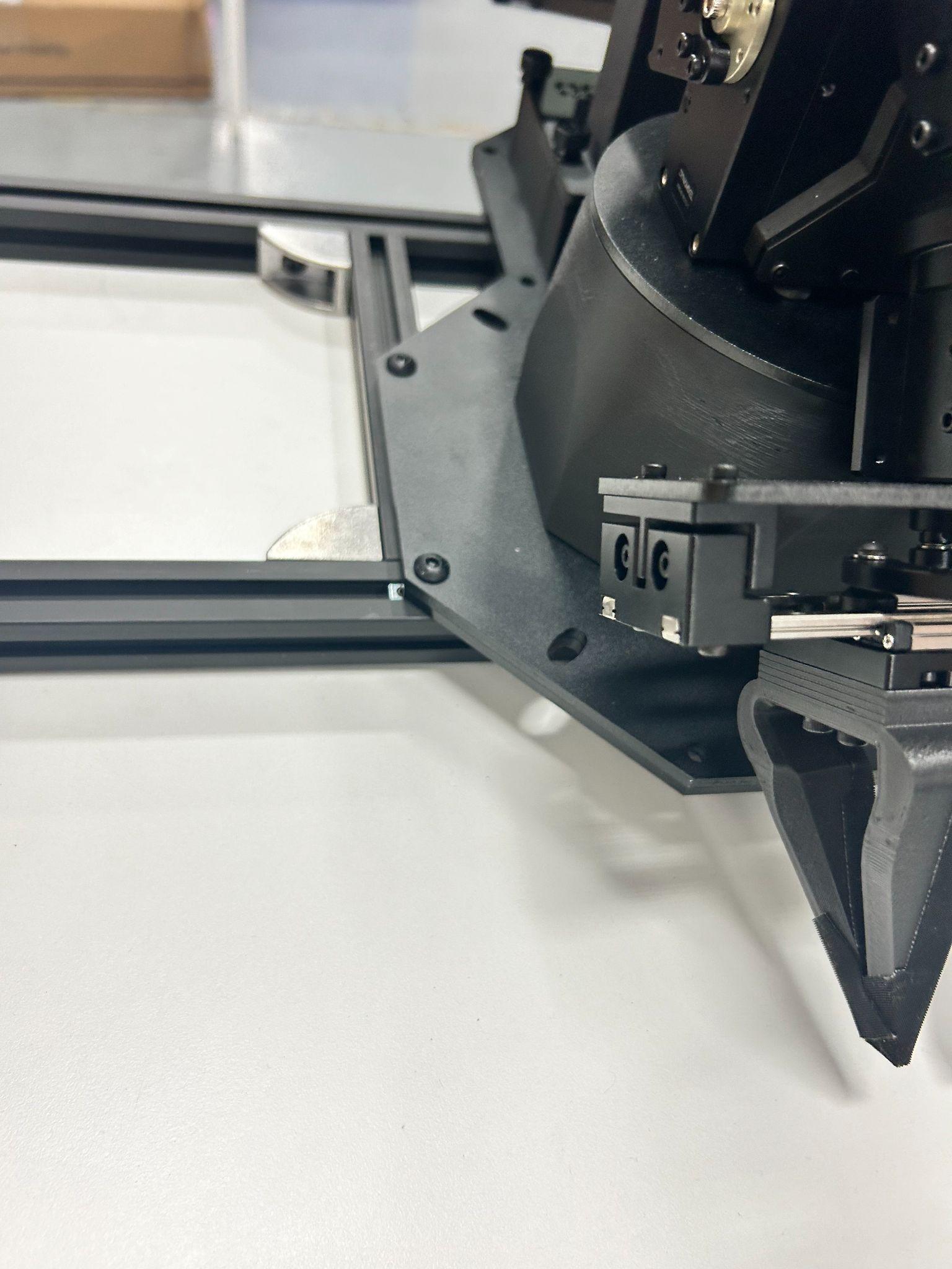
|
|
Use (4x) M5x14s bolts for each ViperX Arm to install into AA/AB SUB-ASSEMBLY.
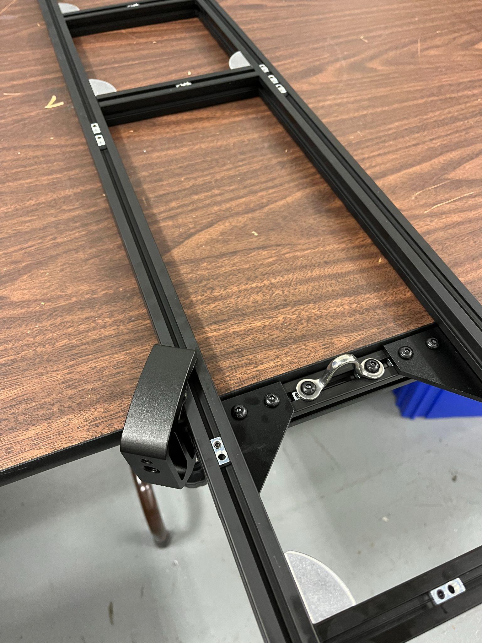
10) Install Pulley System
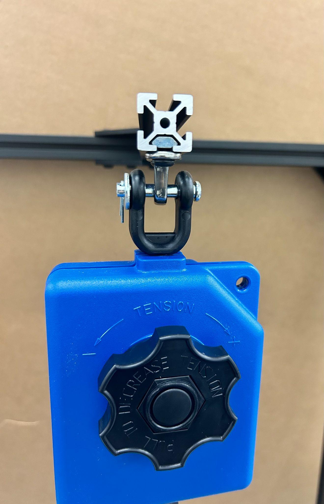
Install AERO-MOTIVE GRAVITY COMPENSATORS to the 200 G BARS.
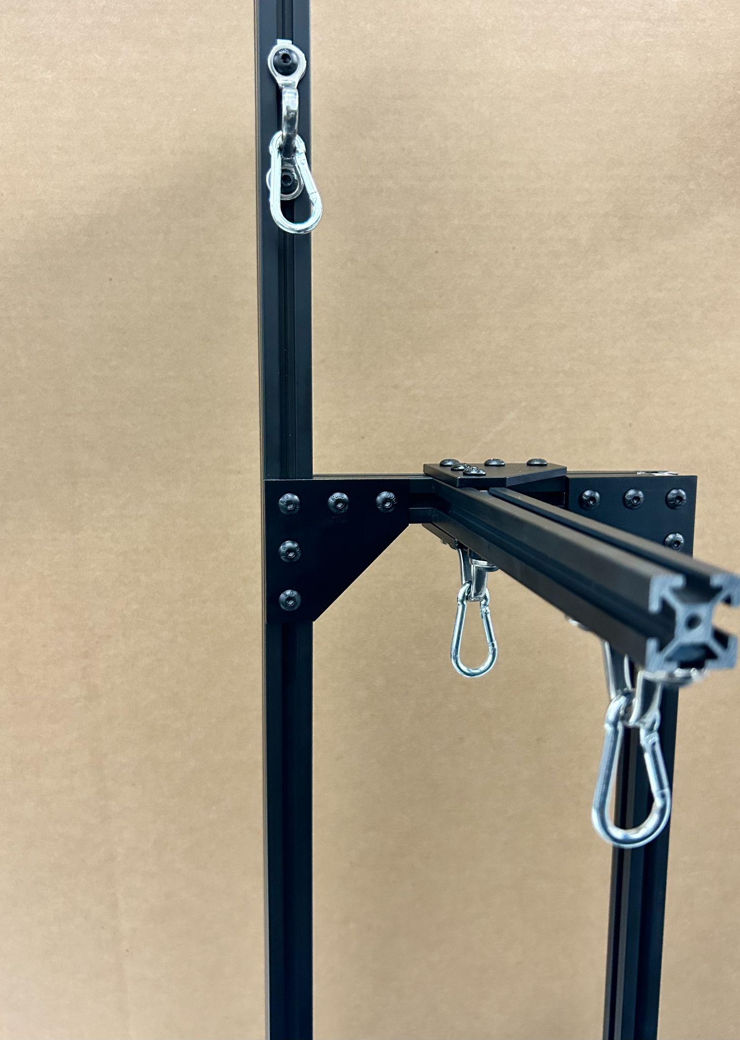
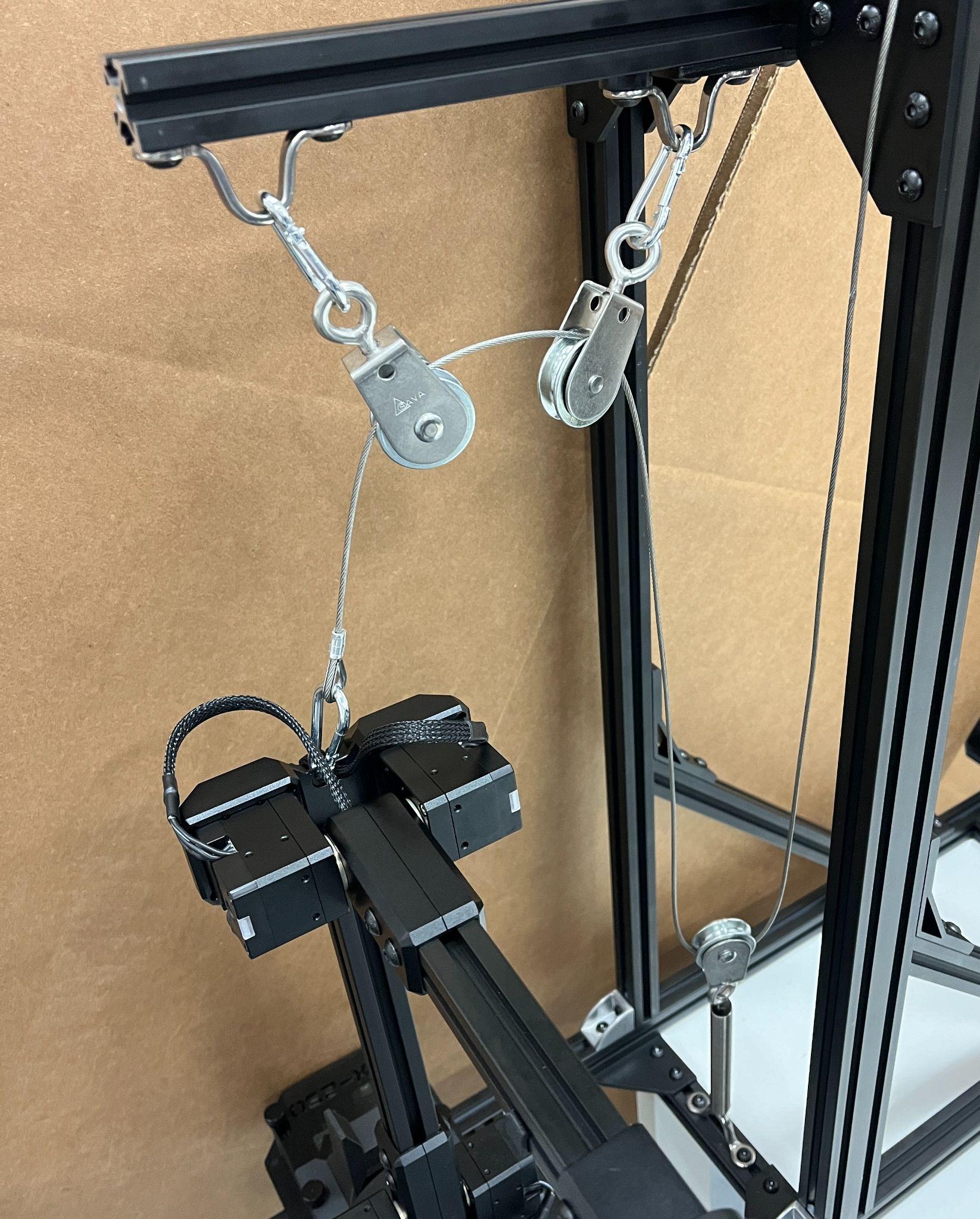
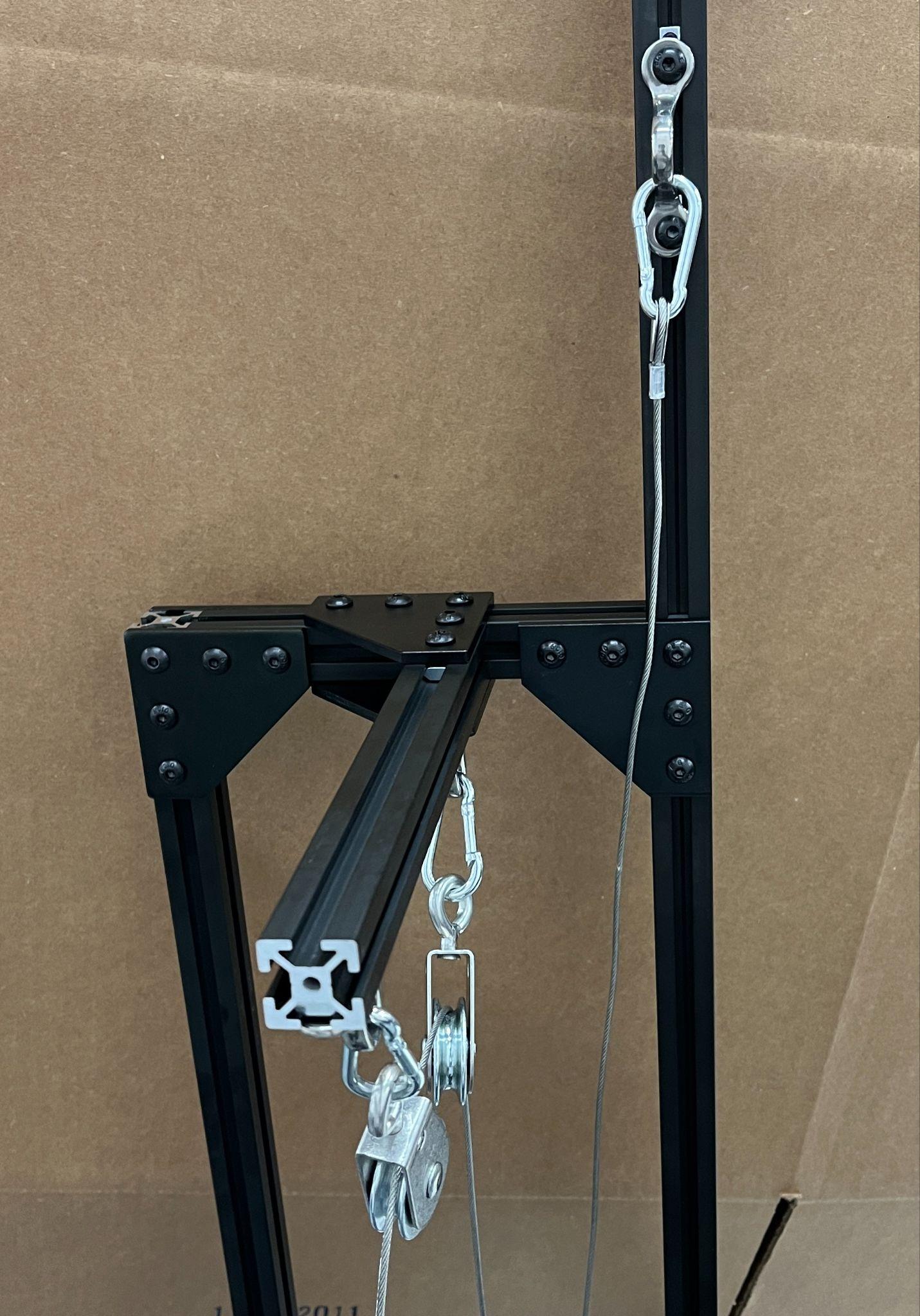
Install CARABINERS at ROPE GUIDES on both H BARS.
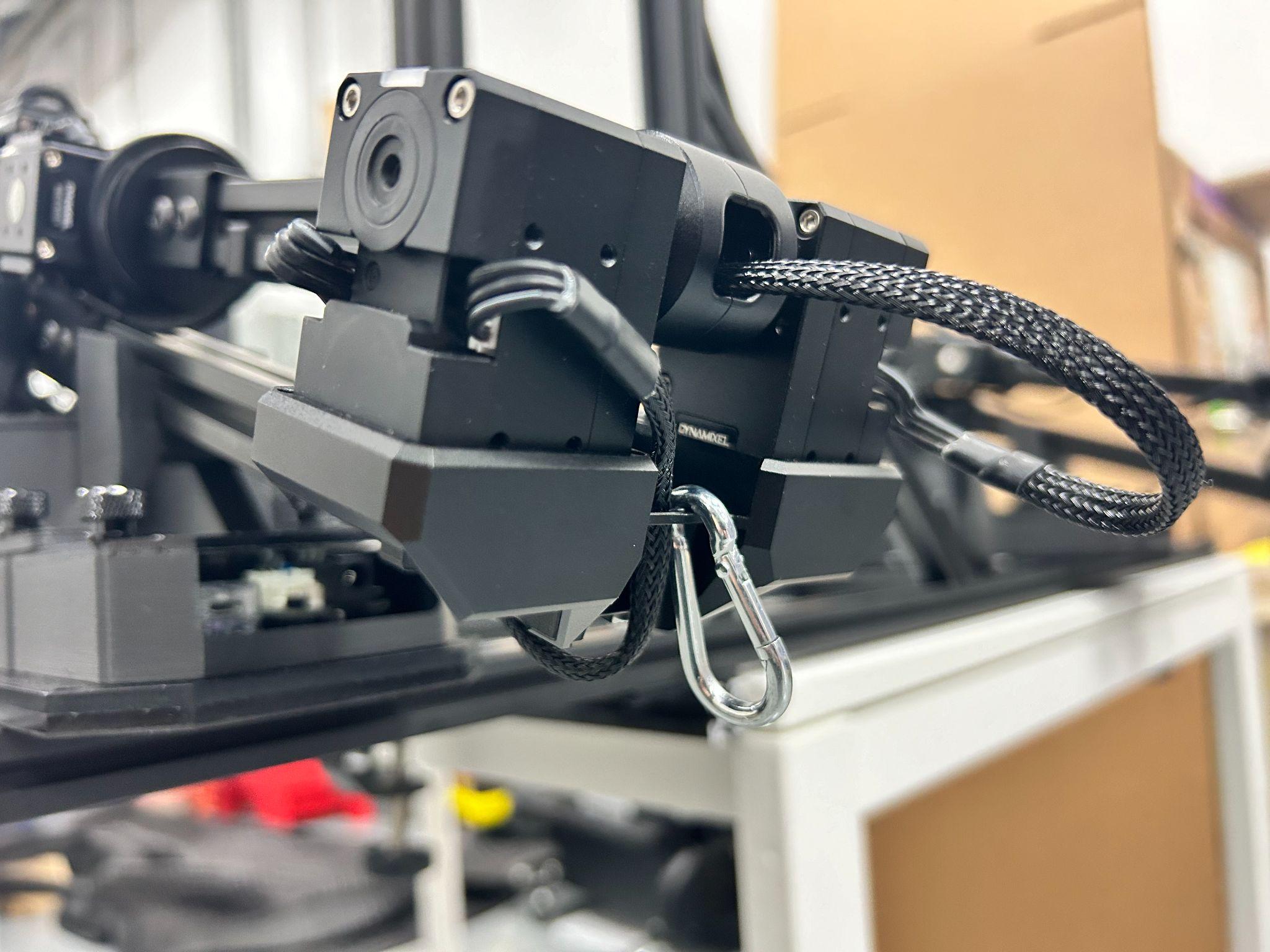
Install CARABINER onto both WidowX Arms.
|
|
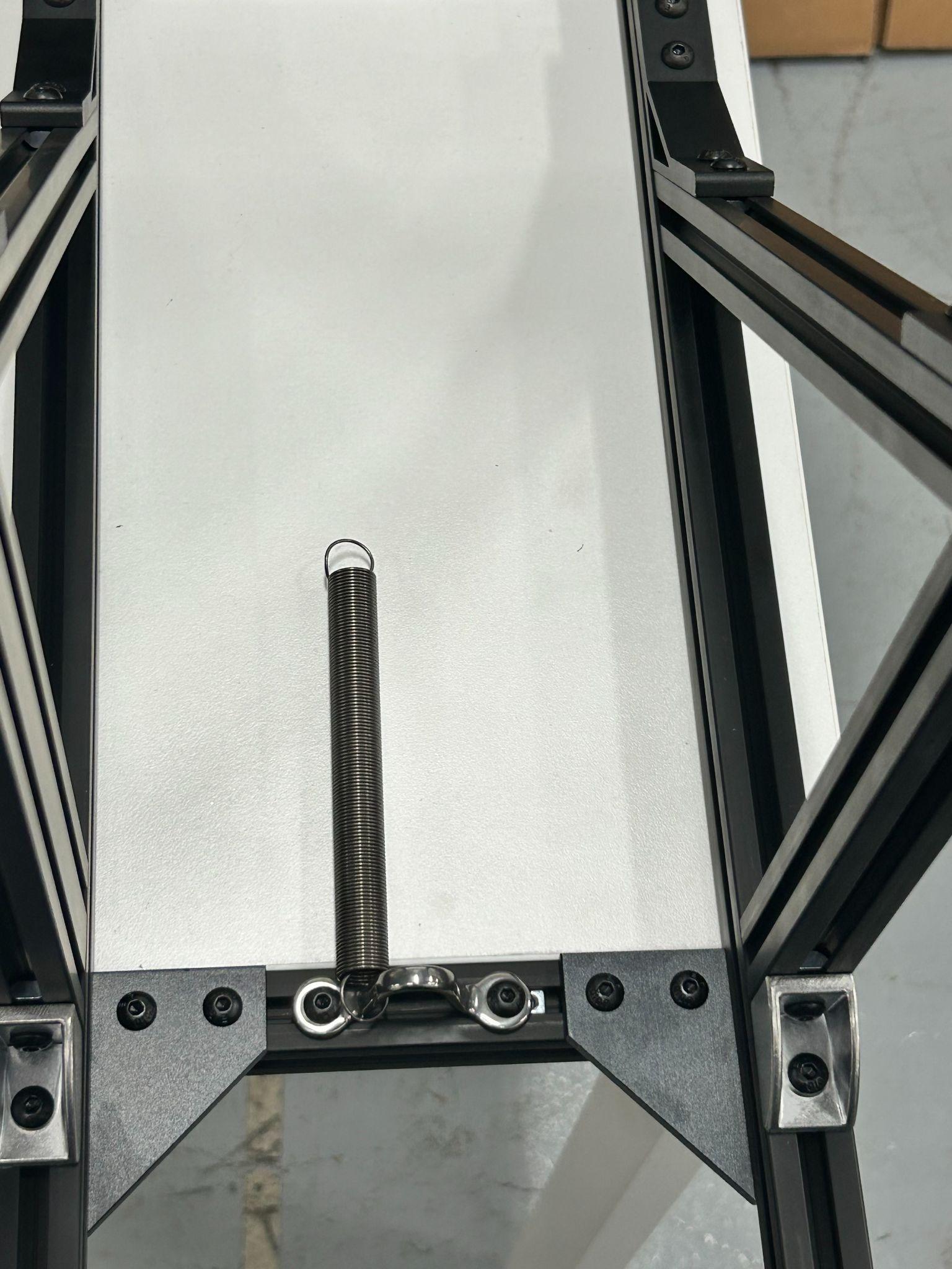
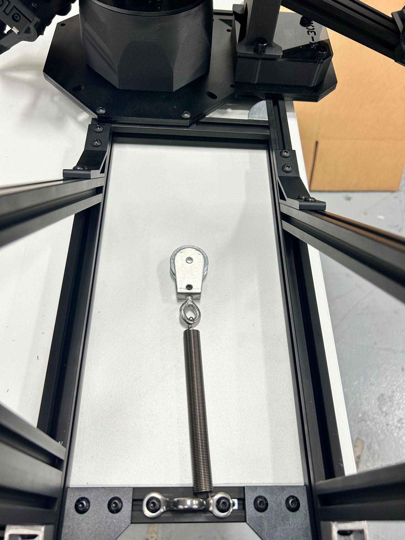
Install SPRINGS into both ROPE GUIDES at the front 1220 BAR with a PULLEY at the end.
|
|
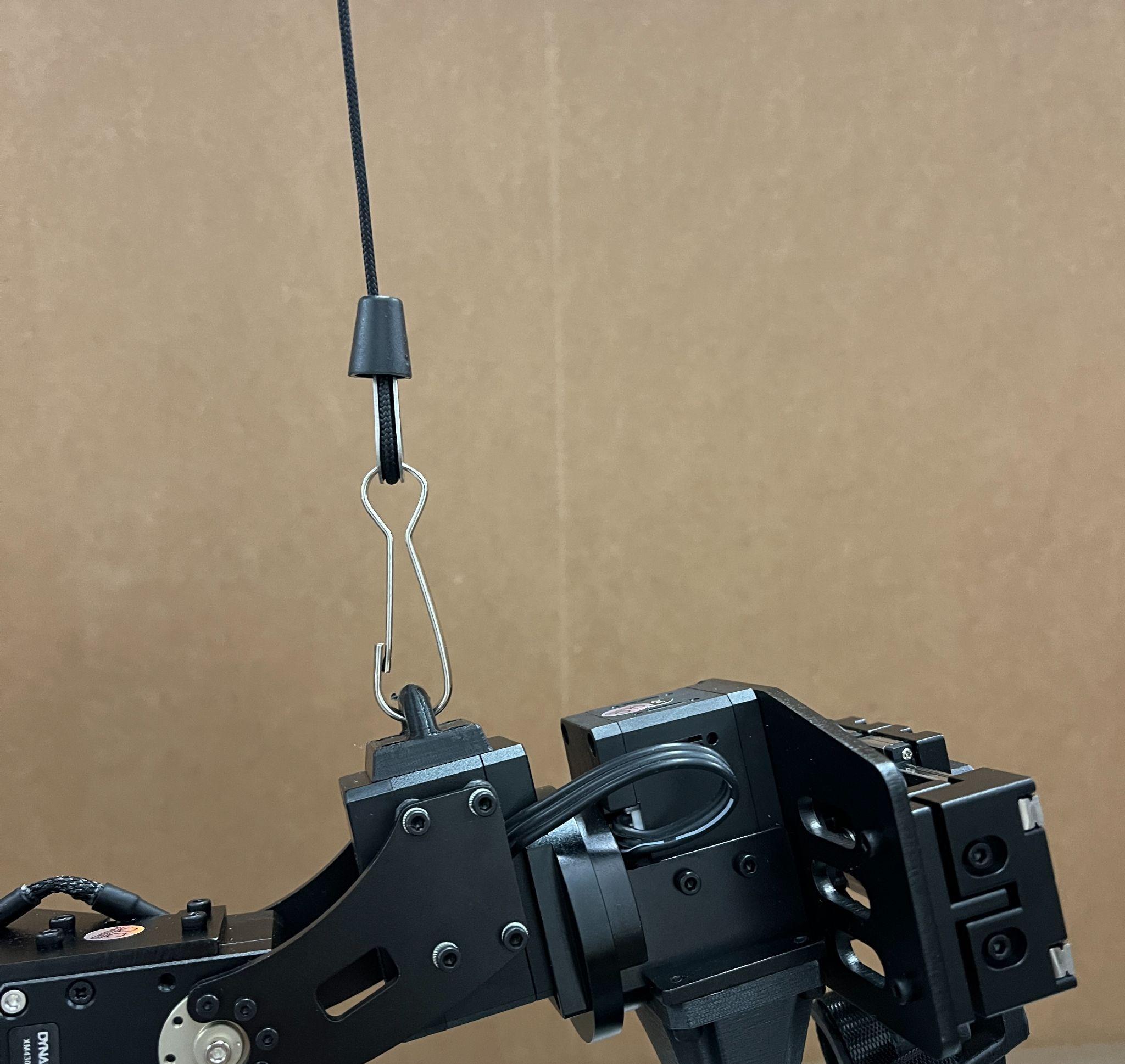
Connect 110mm STEEL CABLE from WidowX Arm to top ROPE GUIDE.
Attach cable from GRAVITY COMPENSATORS to WidowX Arm.
11) Add Camera Mounts
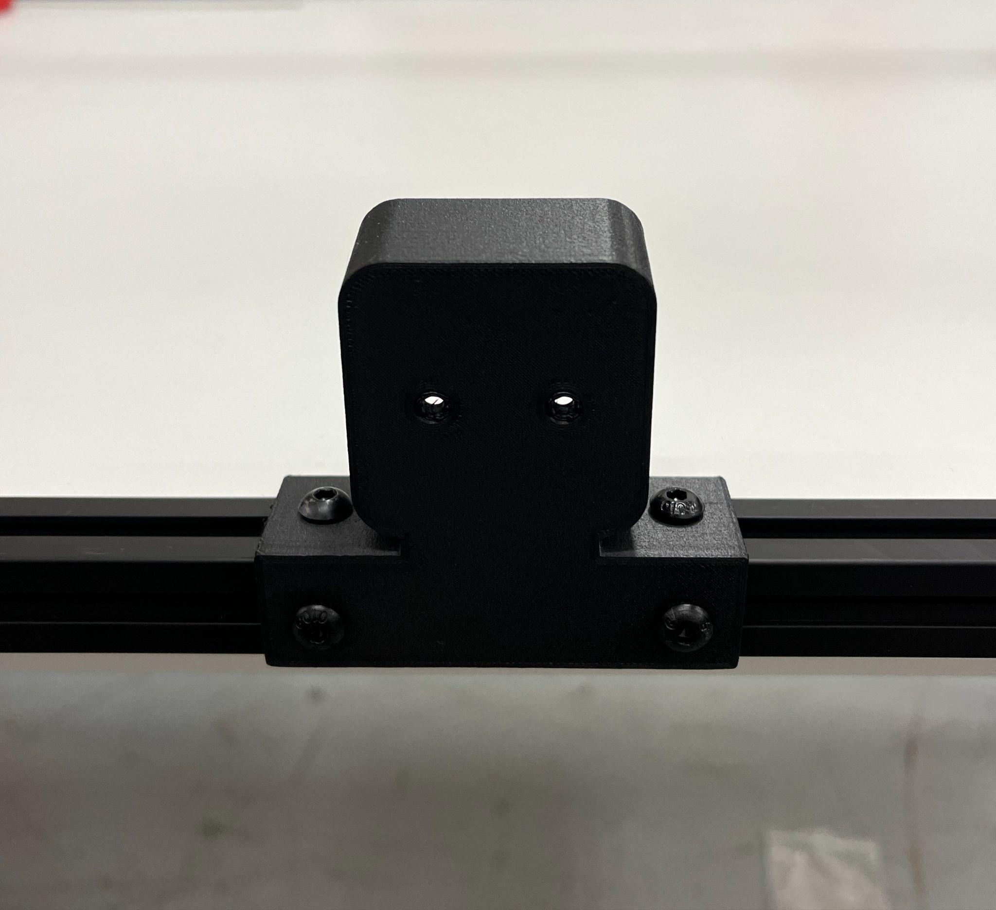
Use (4x) M5x8s bolts to install camera mount.
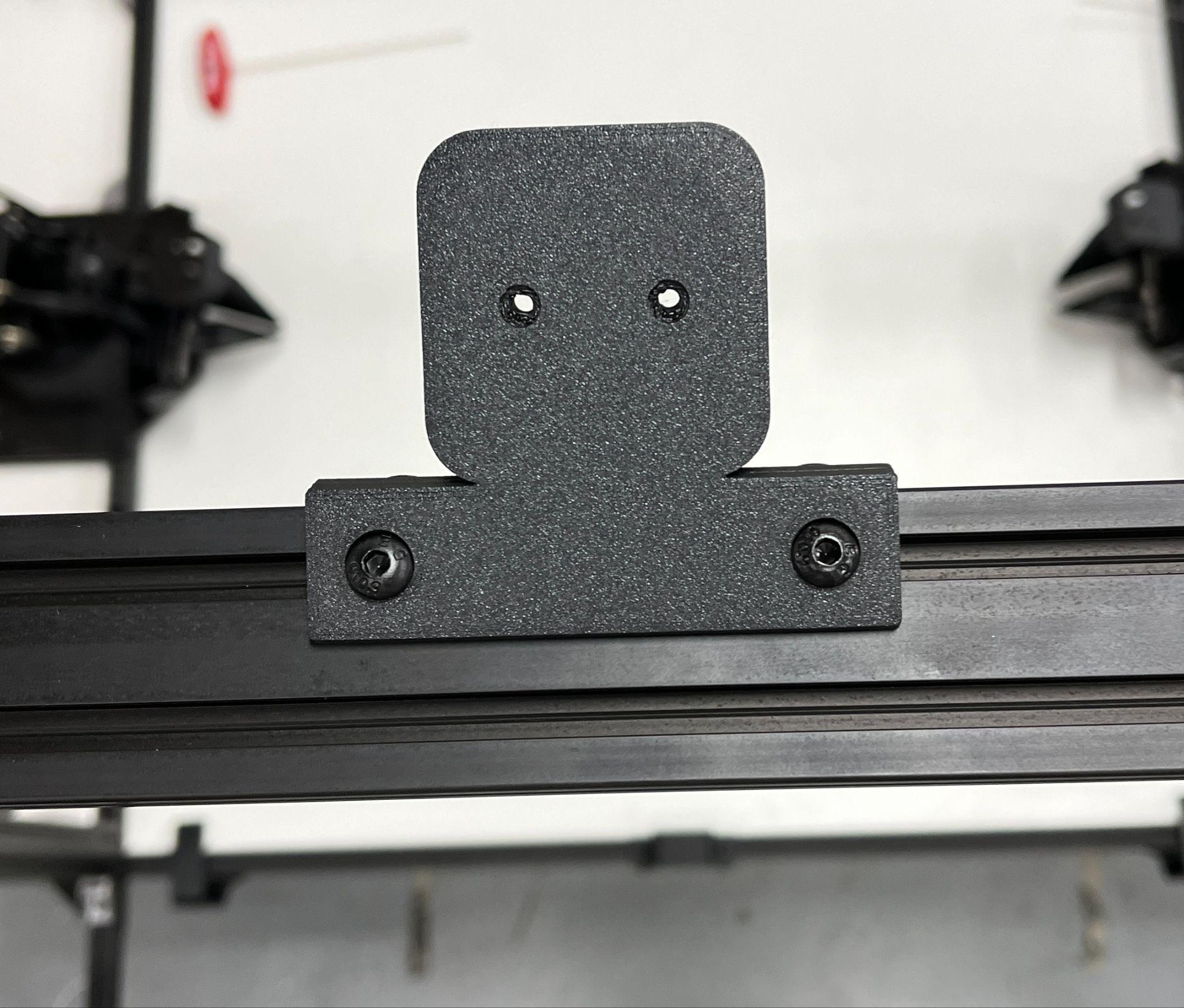
Use (4x) M5x8s bolts to install camera mount.
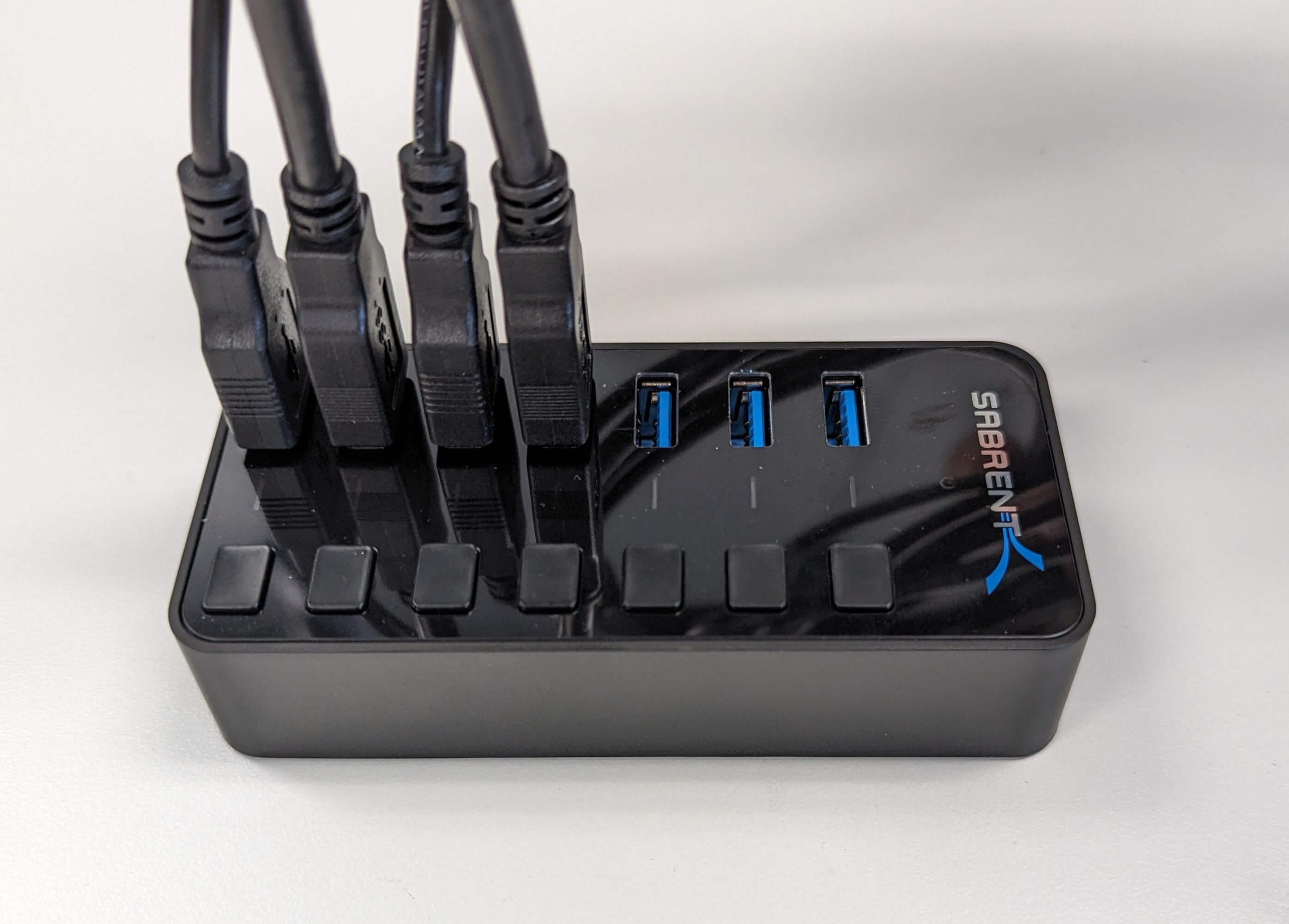
12) Wiring
We have found that alternating arm and camera cables on the hub on the side opposite the Sabrent logo provides the most reliable connection for all devices.